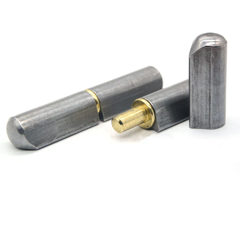
Put the hinge positions on one drawing
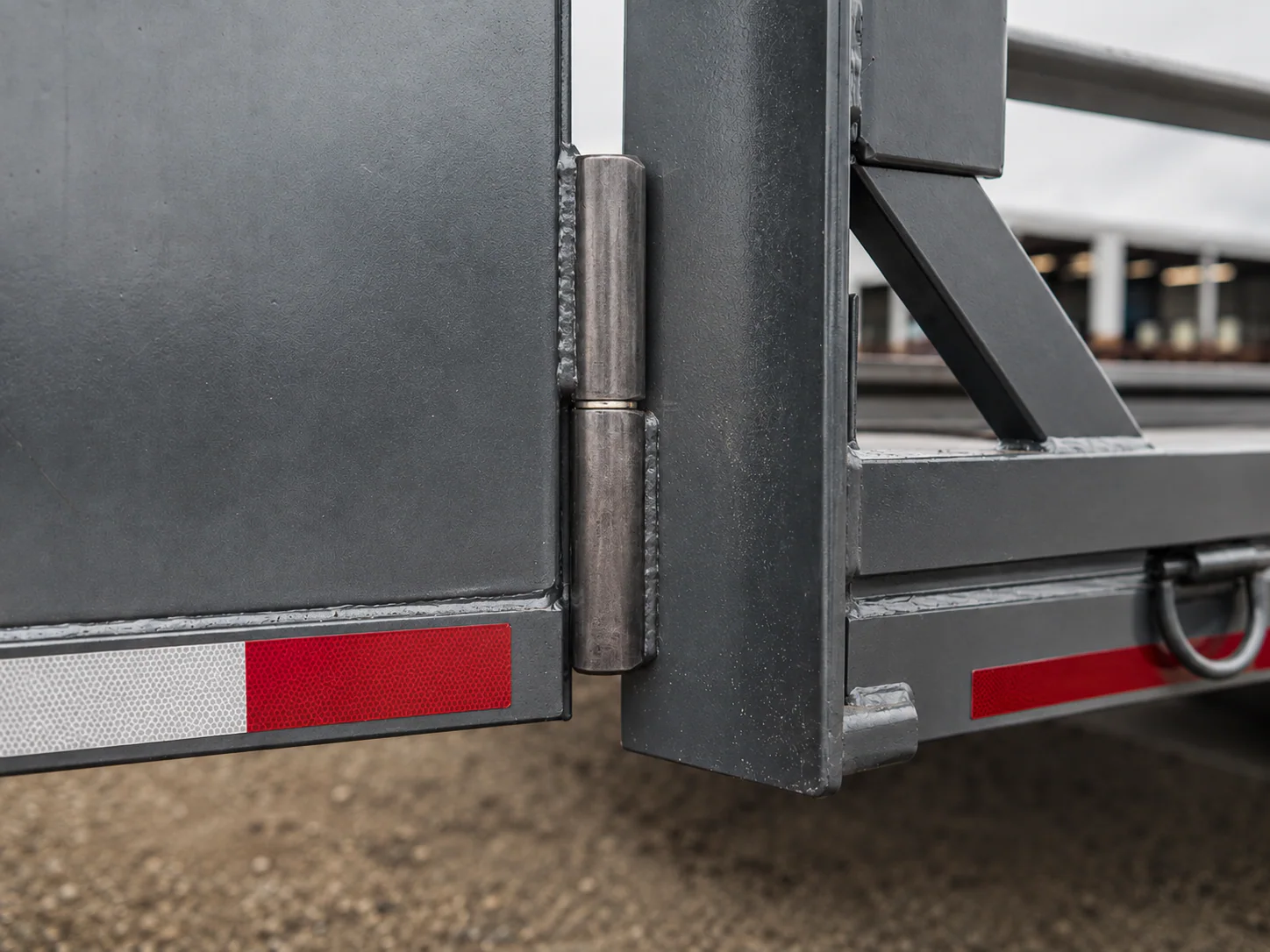
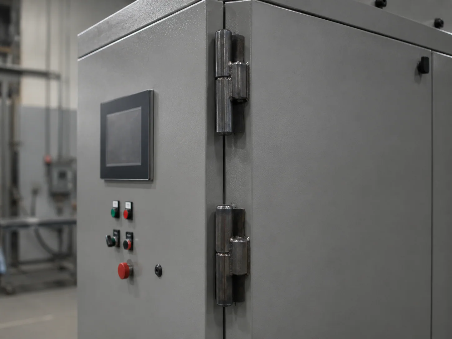
For a door carried by multiple hinges, their pivot axes need to work together. Show the proposed hinge positions and axis on the door-and-frame drawing. Checking each loose hinge separately does not establish that the assembled layout is aligned.
Guden’s selection guidance identifies pin alignment as an installation consideration. Apply that as a question for the assembly drawing; it does not supply a numerical alignment allowance for a HINGETRA product.
Check the opening path
Mark the required open and closed positions. Include the frame return, door fold, seals and nearby structures that could obstruct movement. If a narrow drawing crops away the surrounding assembly, add a wider view rather than assuming the area is clear.
- Where is the pivot axis relative to the door edge and frame?
- What is the required open position?
- Which nearby part comes closest during movement?
- Does the door need space for another operation while open?
Check how a separable hinge comes apart
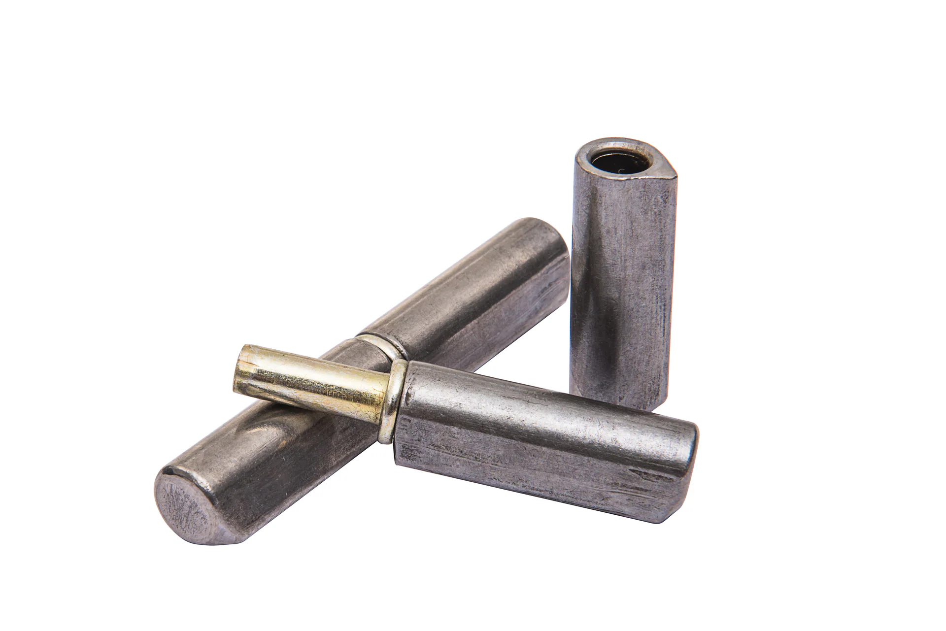
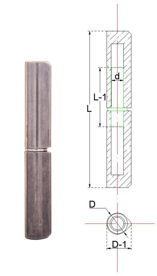
First confirm that the chosen construction is intended to separate in the way you need. For a design in which one half slides off a pin, the free path must allow the engaged parts to disengage. Base that distance on the actual hinge drawing rather than the overall body length.
Show the removal direction and nearby obstruction on the same view. A top cover may limit an upward path; a neighboring assembly may limit a sideways path. Include the space needed to handle the door after the hinge parts separate.
Orientation also affects how a removable assembly remains engaged. Guden’s removable-hinge guide distinguishes vertical and horizontal arrangements. Have the complete arrangement, including any required retention, reviewed for its intended orientation.
Separate geometry review from welding instructions
This checklist identifies information for selection and installation planning. It does not define a weld procedure, fixture setting or acceptance measurement. Those depend on the actual part and fabrication requirements and should be specified by the person responsible for the assembly.
Comparison table Scroll horizontally →
| View | Information to mark |
|---|---|
| Whole door | Hinge count, positions and pivot axis |
| Door-edge section | Frame, moving panel, hinge position and nearby obstructions |
| Open position | Required movement and remaining clearance |
| Removal position | Direction, disengagement travel and handling space |
For a new inquiry, attach these views with the exact product reference. For an existing installation, add photographs and describe where movement becomes restricted. The drawing and RFQ guide helps organize the request without guessing the missing dimensions.