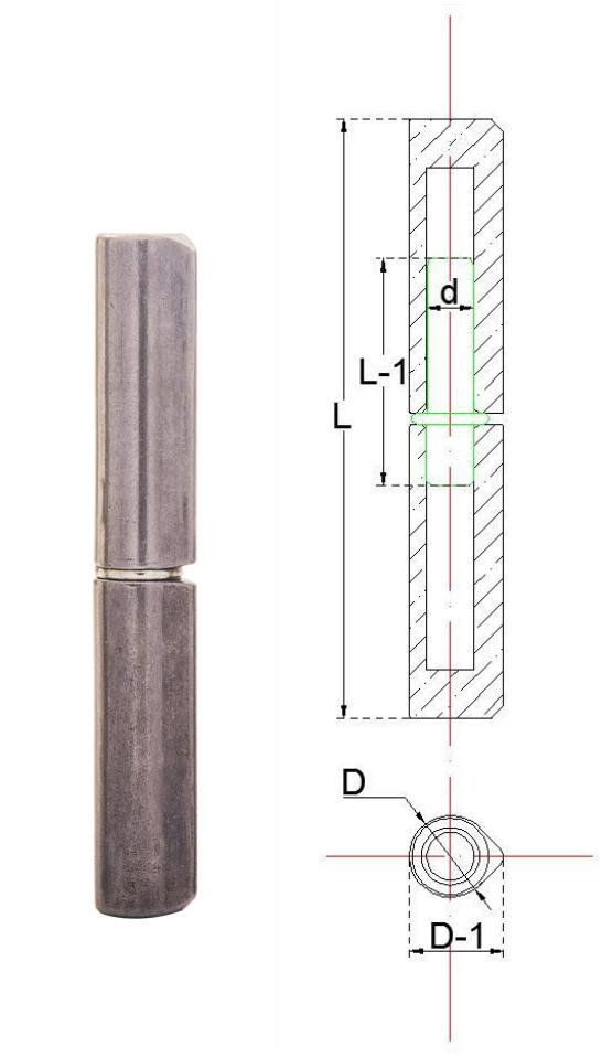
Axial Weight vs. Radial Load: The Dual-Rating Principle
When specifying heavy-duty weld-on hinges (including bullet hinges, barrel hinges, and teardrop profiles), mechanical engineers must evaluate two independent, orthogonal force vectors acting on the hinge axis:
- Axial Load (F_axial): The downward gravitational force exerted parallel to the hinge pin centerline, representing the total dead weight of the door leaf and all attached components.
- Radial Load (F_radial): The horizontal shear force exerted perpendicular to the hinge pin axis, created by the rotational overturning moment of the door's cantilevered mass.
In established industrial practice, heavy-duty hinge manufacturers publish load ratings by explicitly pairing these two independent parameters. For example, in the heavy-duty weld-on hinge engineering catalog published by Kiesler Machine (kieslermachine.com), product models list distinct pairs for door weight and radial capacity, such as model 2500LH rated at 1000 lbs door weight / 400 lbs radial load, model 2100LH at 4000 lbs door weight / 1630 lbs radial load, model 2125LH at 8000 lbs door weight / 3300 lbs radial load, model 2150LH at 13000 lbs door weight / 6820 lbs radial load, and model 2200LH at 20000 lbs door weight / 8800 lbs radial load.
Across these published catalog configurations, the allowable door weight rating is consistently higher than the corresponding radial load capacity. Sizing a hinge installation solely on vertical door weight without evaluating the horizontal cantilever force creates a critical vulnerability: wide doors generate substantial radial reactions that can exceed the pin's bending resistance long before the axial thrust bearing reaches its static weight limit.
Comparison table Scroll horizontally →
| Load Dimension | Primary Direction of Action | Primary Mechanical Hinge Component Loaded | Governing Failure Mode if Undersized |
|---|---|---|---|
| Axial Load (F_axial) | Vertical, parallel to pin centerline | Internal thrust washer, bronze bushing, or bearing interface | Washer galling, accelerated vertical wear, bottom barrel contact |
| Radial Load (F_radial) | Horizontal, perpendicular to pin centerline | Hinge pin shaft and barrel bore contact zone | Pin deflection, bore ovalization, rotational binding, door sagging |
The Three Governing Variables of Hinge Loading
The mechanical stress experienced by a weld-on hinge assembly is governed by three primary geometric and physical parameters:
- Total Door Mass (W): The gross weight of the structural frame, sheet skinning, insulation, internal hardware, glazing, and potential external attachments.
- Horizontal Center of Gravity Distance (d_cg): The horizontal distance measured from the theoretical centerline of the hinge pivot pin to the center of mass of the door assembly. For uniform rectangular leaves, this distance is approximately half the door width (W_door / 2).
- Vertical Hinge Spacing (S): The center-to-center vertical distance between the outermost hinge pivot points on the frame jamb.
The horizontal overturning moment generated by the cantilevered door leaf is equal to the total door weight multiplied by the horizontal distance to the center of gravity (M = W × d_cg). This overturning moment must be resisted by an equal and opposite force couple acting across the vertical hinge spacing (S).
Comparison table Scroll horizontally →
| Design Modification | Impact on Axial Load (F_axial) | Impact on Radial Load (F_radial) | Corrective Engineering Countermeasure |
|---|---|---|---|
| Increasing Door Width | Proportional to added material weight | Increases directly with extended cantilever moment arm | Increase vertical hinge spacing (S) or step up to a larger pin diameter |
| Increasing Door Height (same width) | Proportional to added material weight | Decreases if vertical hinge spacing (S) is expanded proportionally | Take advantage of available height to maximize vertical hinge spacing |
| Decreasing Hinge Spacing (S) | No change | Increases sharply due to reduced moment resistance arm | Avoid tight hinge clusters unless door width is narrow or supplemental hinges are added |
| Adding Dense Off-Center Hardware | Increases total weight directly | Shifts center of gravity outward, increasing radial torque | Recalculate exact center of gravity (d_cg) rather than assuming center-point |
Mathematical Calculation Framework and Illustrative Sizing Example
To select the appropriate weld-on hinge size and verify that both axial and radial working limits are maintained, structural designers evaluate the static force equations for a standard two-hinge vertical installation.
Static Equilibrium Equations (Standard Two-Hinge Setup)
- Axial Force per Assembly: F_axial, total = W_door. In theoretical dual-hinge models, vertical load may be shared; however, due to fabrication tolerances, a single thrust interface frequently supports the primary vertical mass during initial seating.
- Radial Reaction Force at Top Hinge (Tension / Outward Pull): F_radial, top = (W_door × d_cg) / S
- Radial Reaction Force at Bottom Hinge (Compression / Inward Push): F_radial, bottom = (W_door × d_cg) / S
Step-by-Step Illustrative Example Calculation
Note: The dimensions, weights, and values in this section are presented solely as a hypothetical engineering example to demonstrate calculation methodology.
Step 1: Calculate Axial Load Requirement. The total static axial load is equal to the assumed door weight: F_axial = 300 kg.
Step 2: Calculate Radial Reaction Force. Using the moment equilibrium formula: F_radial = (300 kg × 600 mm) / 1800 mm = 100 kg.
Step 3: Evaluate the Sizing Outcome. In this hypothetical configuration, each hinge must resist a horizontal radial shear force of 100 kg at the pin, while the hinge pair carries the 300 kg axial dead weight. If the vertical spacing (S) in this hypothetical setup were reduced from 1800 mm to 900 mm while retaining the same 300 kg door weight and 600 mm center of gravity, the radial force on each hinge would double: F_radial, reduced spacing = (300 kg × 600 mm) / 900 mm = 200 kg. This comparison demonstrates why maximizing vertical center-to-center spacing (S) is the most effective mechanical strategy for reducing pin stress on heavy access doors.
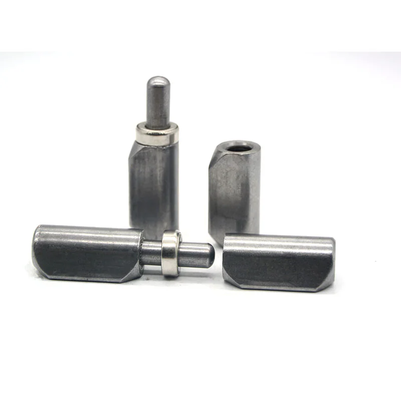
Hinge Distribution Strategy: Two-Hinge vs. Three-Hinge Layouts
Deciding whether to install two, three, or four weld-on hinges per door leaf involves balancing radial force mitigation, leaf rigidity, and coaxial alignment accuracy during welding.
Two-Hinge Configuration: The Statically Determinate Baseline
- Guaranteed Axis Collinearity: Two pivot points mathematically define a single straight line in three-dimensional space, preventing internal hinge binding caused by manufacturing runout.
- Predictable Force Distribution: The top hinge acts purely in radial tension, the bottom hinge acts in radial compression, and vertical thrust load transfers directly through the designated washer face.
- Unobstructed Lift-Off: For detachable or slip-joint bullet hinges, a two-hinge setup allows straightforward vertical removal without binding.
Three-Hinge Configuration: Spacing Distribution Strategies
Adding a third hinge is common on tall doors, heavy structural leaves, or flexible sheet metal enclosures. However, the physical placement of the third hinge alters how forces are distributed:
Comparison table Scroll horizontally →
| Layout Strategy | Hinge Placement Description | Primary Engineering Objective | Critical Fabrication Considerations |
|---|---|---|---|
| Equidistant Spacing | One top, one center, one bottom (equal vertical gaps) | Resisting center-leaf warping or bowing caused by door seals or weatherstripping | Center hinge contributes minimally to overturning moment resistance; requires precise alignment jigging |
| Clustered Top Spacing | Two hinges positioned close together near the top jamb, one hinge at the bottom | Sharing the high horizontal tension load at the top of wide or heavy cantilevered leaves | Upper two hinges must be welded with a continuous ground mandrel to prevent pin bind |
Dynamic Operating Factors and Environmental Conditions
Static calculations establish the baseline load requirement; however, real-world industrial installations experience dynamic stresses that require additional engineering allowances. When determining final hinge capacity, consider the following operating factors:
- Dynamic Shock Loads and Vibration: Mobile applications—such as utility trailers, service truck toolboxes, and engine compartment covers—subject hinge pins to continuous road vibration and vertical acceleration forces.
- Wind and Aerodynamic Overturning Loads: Exterior perimeter gates, architectural gates, and rooftop enclosures experience large horizontal wind loads. Wind pressure acting across the full surface area of a closed or opening gate creates substantial horizontal reaction forces that add directly to the static radial cantilever load.
- High Operating Cycle Rates: High-frequency access doors in industrial manufacturing lines require thrust interfaces with continuous lubrication provisions, such as integrated grease fittings or self-lubricating sintered bronze bushings, to prevent accelerated washer wear that leads to door drop.
- Corrosion and Washdown Exposure: Coastal marine environments, chemical processing plants, and food washdown facilities accelerate friction and galvanic degradation. In these conditions, passivated 304 or 316 stainless steel weld-on hinges prevent corrosive seizure.
Technical Parameters Required for Manufacturer Sizing and RFQ
To receive an accurate engineering recommendation and formal quotation from HINGETRA for standard or custom weld-on hinges, prepare a technical data package containing the following application variables:
- Physical Door Leaf Dimensions: Total door height, width, and sheet thickness.
- Estimated Total Assembly Weight: Complete weight including frames, infill, hardware, and accessories.
- Horizontal Center of Gravity (d_cg): Measured or estimated distance from hinge pivot line to center of mass.
- Planned Hinge Spacing (S): Center-to-center distance between top and bottom hinge locations.
- Operating Frequency & Duty Cycle: Anticipated cycles per day (e.g., occasional maintenance access vs. continuous industrial cycling).
- Environmental Exposure: Indoor climate-controlled, outdoor sheltered, direct coastal marine, chemical washdown, or extreme temperature ranges.
- Material & Profile Preferences: Carbon steel, 304 stainless steel, 316 stainless steel, or aluminum body; round barrel vs. teardrop profile; fixed pin vs. lift-off detachable pin.
- Lubrication Requirements: Standard sealed cavity vs. integrated grease fittings.
For dimensional detailing on engineering drawings, review our guide on Preparing Hinge Drawing Dimension Requests, consult our overview of Weld-On Hinge Sizes and Dimensional Standards, or explore our complete selection of Industrial Weld-On Hinges for comprehensive selection support.
Frequently Asked Questions
Why is radial load often the governing factor rather than door weight when sizing weld-on hinges?
While door weight acts vertically downward as pure axial shear, wide doors create a horizontal cantilever overturning moment. This moment exerts horizontal pulling tension on the top hinge and pushing compression on the bottom hinge. On wide or heavy doors, these radial reaction forces can exceed the shear strength or bending limit of the pin shaft well before the vertical weight capacity of the thrust washer is reached.
How does vertical hinge spacing directly affect the force exerted on each hinge pin?
Radial reaction force on the hinges is inversely proportional to the vertical distance between the top and bottom hinge centerlines. Doubling the vertical spacing between hinges halves the horizontal force couple acting on each hinge pin. Conversely, placing hinges close together dramatically amplifies radial force on the pins, leading to pin deflection and premature hinge binding.
When should a third weld-on hinge be installed near the top rather than in the center?
Placing a third hinge close to the top hinge is recommended for wide or heavy doors where the primary structural challenge is high horizontal cantilever tension. In this layout, the two upper hinges share the outward radial pulling force. In contrast, positioning the third hinge in the exact center is primarily used on tall doors to prevent middle-leaf bowing or warping against door gaskets.
How can fabricators ensure coaxial alignment when welding three or more hinges on a single door?
When welding three or more hinges, fabricators must maintain a strictly collinear rotational axis across all hinge barrels to prevent mechanical binding. The standard shop method is to slide a single, continuous, precision-ground alignment mandrel through all hinge barrels during positioning and tack welding. Welding barrels individually without a shared alignment rod frequently results in angular runout that causes door binding.
What mechanical information is required by a hinge manufacturer to calculate and recommend the correct hinge size?
To perform an accurate load calculation, a hinge manufacturer requires the total door weight, overall door width and height, the horizontal distance to the door's center of gravity, the proposed vertical hinge spacing, the operating duty cycle, and environmental operating conditions (such as wind exposure, washdown chemicals, or marine salt spray).