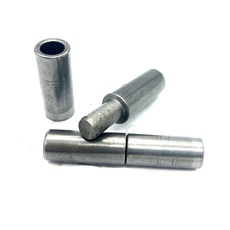
Why Thin Sheet Metal Warps During Hinge Welding
Welding a solid steel hinge barrel to a thin sheet metal door skin brings together two fundamentally mismatched thermal masses. The solid hinge body requires sufficient heat input to achieve solid root penetration, while the thin sheet heats rapidly and expands across a localized zone. Because the surrounding unheated sheet resists this localized thermal expansion, the heated area yields in compression. Upon cooling, the weld zone contracts, leaving high residual tensile stresses that pull the thin sheet into visible waves, angular distortion, or oil-canning (snap-through buckling).
Beyond cosmetic skin distortion, uncontrolled heat input creates mechanical failures inside the hinge itself:
- Bore Shrinkage and Pin Seizure: Excessive continuous welding around the hinge barrel causes the tubular body to contract radially upon cooling, pinching the internal pin shaft and creating stiff rotation or complete seizure.
- Washer Annealing or Degradation: Leaving internal brass, bronze, or polymer thrust washers in place during welding anneals the metal or burns out dry lubricants, resulting in rapid vertical wear once the door enters service.
- Hingeline Misalignment: Angular distortion of the sheet edge tilts the top or bottom hinge barrel relative to the shared rotational axis, causing severe binding that resists manual door opening.
For engineers evaluating mounting methods across production lines, understanding when to weld directly versus when to use mechanical fasteners is critical. Review our detailed comparison on Weld-On vs. Bolt-On Hinges to establish the structural baseline for your enclosure design.
Why does welding a hinge directly to thin enclosure sheet cause visible panel warping?
Panel warping occurs because the thick solid hinge barrel requires substantial welding heat to establish root fusion, while the thin sheet metal rapidly overheats and undergoes localized thermal expansion. Constrained by the cooler surrounding sheet, the hot metal yields under compressive stress. When the weld bead contracts during cooling, residual tensile stress pulls the thin panel out of plane, creating visible waves, diagonal wrinkles, or oil-canning.
Matching Hinge Cross-Section Profiles to Sheet Metal Joint Geometry
The geometric cross-section of the weld-on hinge body directly determines how welding heat transfers into the sheet metal substrate and where the resulting fillet weld is positioned.
Comparison table Scroll horizontally →
| Hinge Body Profile | Contact Interface with Sheet Metal | Heat Transfer and Fillet Location | Primary Application Suitability |
|---|---|---|---|
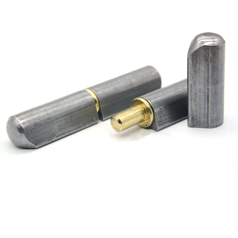
| Teardrop Profile with Integrated Weld Flange | Extended tapered lip rests directly against the sheet face or bent door return flange | Weld arc strikes the extended tip of the flange, keeping intense arc heat away from the critical cylindrical pin bore | Thin-wall electrical enclosures, formed sheet steel doors, and lightweight inspection access panels |
| Standard Cylindrical Bullet / Round Barrel | Curved tangent line creates a narrow V-groove against a flat sheet surface | Weld fillet sits directly along the cylindrical barrel wall; requires controlled stitch passes or backing plate heat absorption | Heavy sheet metal leaves, structural door frames, and applications using internal backing plates |
| Flat-Back Strap or Block Profile | Wide, flat mating surface provides substantial surface contact area | Distributes clamping pressure over a broader zone; requires balanced stitch passes on opposing edges | Medium-to-heavy sheet enclosures and structural box-tubing jambs |
Selecting between hinge cross-sections depends on joint access and backing thickness. For lightweight formed panels and narrow door returns, the teardrop profile deposits the weld bead along an extended welding lip, allowing arc heat to dissipate along the flange before reaching the internal pin bore while providing built-in standoff clearance for door gaskets. Conversely, standard cylindrical round barrel hinges are standard practice on heavier sheet assemblies, structural box-tube jambs, and designs utilizing internal doubler plates, where the thicker substrate absorbs welding energy without bore distortion while maintaining a compact, flush exterior profile.
For broader dimensional and structural standards across various barrel configurations, consult our guide on Weld-On Hinge Sizes and Dimensional Standards, or explore our foundational guide on How to Choose Weld-On Hinges.
How do teardrop and cylindrical round barrel profiles differ when welded to sheet metal?
Teardrop profiles feature an extended welding flange that positions the weld bead away from the internal pin socket, providing a thermal buffer and built-in clearance on lightweight formed sheet returns. Cylindrical round barrel hinges weld directly along the barrel tangent, making them ideal for heavier sheet metal leaves, structural perimeter frames, and assemblies reinforced with internal backing plates that readily absorb arc heat.
Reinforcement Plates and Internal Stiffener Design
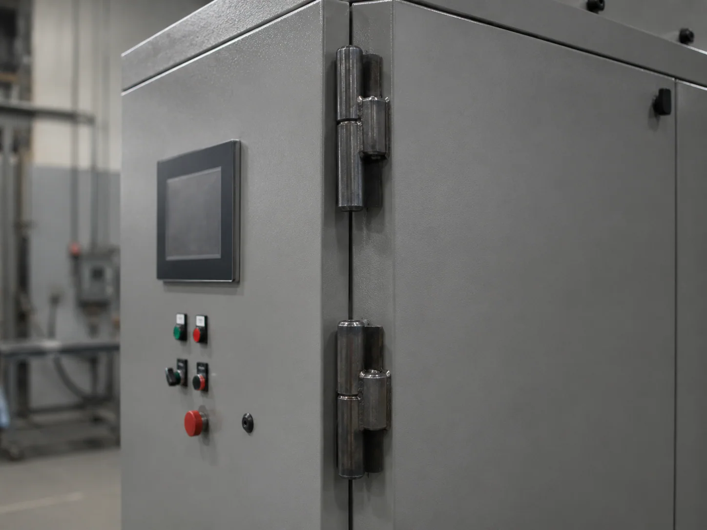
When high-frequency industrial access doors or heavy component-loaded doors are fabricated from thin sheet metal, welding the hinge directly to the unsupported exterior skin creates a structural stress concentration. Opening and closing cycles exert localized fatigue and cyclic bending forces that can tear the thin sheet metal around the weld toes.
To prevent sheet metal fatigue tearing and eliminate panel flexing, structural engineers employ two primary reinforcement techniques:
- Internal Doubler Plates (Backing Pads): A flat structural plate of thicker material is positioned on the unexposed interior face of the sheet metal door skin, directly behind the hinge mounting zone. The doubler plate is plug-welded or stitch-welded to the sheet before the hinge is attached. This composite cross-section distributes the rotational cantilever moment over a broad area of the door skin.
- Attachment to Formed Edge Flanges or Structural Sub-Frames: Rather than mounting hinges to the middle of an unsupported flat panel, the sheet metal door should be designed with hemmed or multi-break formed return flanges. Welding the hinge barrel directly along the stiff corner formed by a perimeter return flange drastically increases resistance to out-of-plane bending and oil-canning.
When sizing the hinge assembly and evaluating how door mass interacts with hinge spacing on structural leaves, reference our detailed guide on Weld-On Hinge Load Capacity and Spacing Calculation.
Comparison table Scroll horizontally →
| Door Construction Method | Load Distribution Behavior | Distortion Risk Level | Required Fabrication Countermeasures |
|---|---|---|---|
| Flat Single-Skin Sheet (No Stiffeners) | High localized point loading at hinge toes; dynamic flexing during door swing | High; severe risk of oil-canning and weld-toe fatigue cracking | Install welded internal doubler plates behind each hinge location prior to barrel attachment |
| Formed Pan Door with Hemmed Box Return | Loads transfer into continuous perimeter corner geometry | Moderate; perimeter bends absorb and resist out-of-plane buckling | Locate hinge weld along the perimeter return flange to leverage natural corner stiffness |
| Tubular Sub-Frame with Sheet Skin Overlay | Hinge welds directly to rigid structural tube; sheet skin carries no primary hinge stress | Low; structural tube acts as an integral heat sink and structural backbone | Weld hinge barrels directly to the underlying structural framework before securing sheet skin |
When is an internal doubler plate required behind a weld-on hinge?
An internal doubler plate is required whenever a hinge is mounted to an unsupported, single-skin sheet metal door that carries significant cantilevered mass, dynamic wind load, or high daily cycling. The backing plate provides the necessary structural thickness to dissipate welding heat, prevents weld burn-through, and distributes cyclic opening forces over a wide surface area to prevent metal fatigue tearing.
Heat Input Management, Stitch Sequencing, and Heat Sinking
Controlling distortion in sheet metal hinge welding is fundamentally an exercise in heat input management. Continuous, unbroken weld beads around the entire hinge barrel are neither necessary nor structurally desirable on sheet metal; full perimeter welding introduces excessive heat that guarantees panel warping and barrel shrinkage.
Fabrication shops follow these proven operational rules to control thermal input:
- Intermittent Stitch Welding: Instead of continuous welding, deposit short, staggered stitch welds. Weld opposite ends or alternate between top and bottom hinges to balance thermal expansion across the door assembly.
- Strict Interpass Cooling Discipline: Allow the welded zone to cool between stitch passes until it can be touched without blistering welding gloves. Depositing a second pass over an already hot hinge barrel compounds thermal expansion and severely shrinks internal pin clearances.
- Conductive Copper or Aluminum Chill Blocks: Clamp heavy copper or aluminum heat sink blocks directly against the sheet metal panel immediately adjacent to the weld joint. The high thermal conductivity of copper rapidly draws heat away from the thin steel, narrowing the heat-affected zone and preventing localized panel buckling.
- TIG (GTAW) vs. Pulsed MIG (GMAW) Process Control: For thin stainless steel or carbon steel sheet metal enclosures, precision TIG welding with tight arc length or Pulsed MIG with low average heat input provides superior control over molten puddle freeze rates compared to standard short-circuit MIG.
Ensuring chemical and thermal compatibility between the hinge material, welding filler rod, and sheet metal panel is essential for crack-free joints. Review our detailed reference on Weld-On Hinge Materials and Finishes for carbon steel, austenitic stainless steel, and marine-grade stainless steel pairing rules.
How does stitch sequencing and heat sinking prevent panel distortion during hinge welding?
Stitch sequencing limits heat buildup by depositing short, staggered weld beads across alternating locations, allowing interpass cooling between passes. Clamping heavy copper or aluminum chill blocks adjacent to the weld seam rapidly conducts heat away from the thin steel panel, keeping the heat-affected zone narrow and preventing the thermal expansion that leads to panel warping.
Clamping Fixtures, Gap Spacing, and Pin Bore Protection
Proper mechanical preparation before striking the welding arc eliminates the majority of downstream alignment defects and rework.
Fabricators follow a strict setup protocol when mounting hinges to sheet metal doors and cabinets:
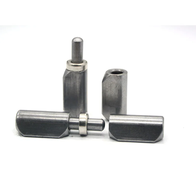
- Disassemble Internal Components Prior to Welding: Never weld a hinge while internal brass, bronze, or polymer thrust washers and grease seals are installed. High welding heat destroys washer lubrication, anneals soft metals, and melts non-metallic seals. Separate the male pin barrel and female barrel socket, or remove the washer entirely during structural welding. For detailed washer selection criteria, consult our technical guide on Bearing, Pin, and Washer Selection for Weld-On Hinges.
- Maintain Coaxial Alignment with Mandrels: When welding two or more hinges along a door jamb, clamp a continuous, ground alignment mandrel through all barrels during tack welding. This ensures perfect collinearity and avoids the pin binding detailed in our guide on Weld-On Hinge Alignment and Removal Clearance.
- Use Perimeter Shims to Set Door Clearance Gaps: Clamp the sheet metal door inside its mating frame jamb with uniform shims placed around the perimeter gap before tack welding. This preserves the operational clearance required for smooth door swing and gasket compression.
- Shield Internal Bores from Spatter and Powder Coating: Protect female barrel internal threads, grease zerk ports, and pin bores from weld spatter using anti-spatter paste or ceramic backing plugs. Prior to powder coating, insert high-temperature silicone masking caps to prevent paint buildup from bridging internal running clearances.
What steps must fabricators take to protect internal hinge components and pin bores during welding?
Fabricators must completely remove internal thrust washers, bearing rings, and grease seals prior to final welding to prevent thermal destruction. Additionally, align multiple barrels with a continuous rigid mandrel during tack welding, shield pin bores and grease zerk ports with anti-spatter protection, and seal barrel sockets with high-temperature silicone masking plugs prior to post-weld powder coating.
Engineering Drawing Callouts and Fabricator Checklist
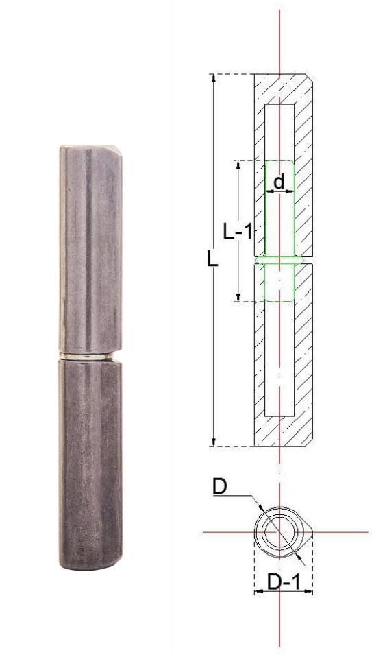
Preventing hinge installation failures on production sheet metal lines begins on the 2D CAD drawing. Rather than relying on generic shop notes such as "weld hinges securely," engineering drawings should provide explicit callouts covering hinge profile, weld pitch, and heat management requirements.
For comprehensive instructions on formatting 2D CAD callouts, tolerances, and submittal drawings for custom hinge manufacturing, review our dedicated resource on Preparing Hinge Drawing Dimension Requests. To evaluate when standard catalog hardware meets your enclosure needs versus when modified dimensions are required, read Standard vs. Custom Weld-On Hinges. For heavy industrial gate, trailer, or specialty enclosure configurations, explore our guide on Weld-On Hinges for Gates, Trailer Doors, and Ramps, or review our enclosure-focused analysis on Weld-On Hinges for Machine Enclosures.