Kinematic Fundamentals of Industrial Hinged Joints
In mechanical engineering, a hinged joint functions as a single-axis revolute kinematic pair that constrains five degrees of freedom while permitting controlled angular rotation about a primary rotational centerline. Unlike consumer hardware, an industrial hinged joint must sustain complex combined mechanical loads across extended operational cycles without plastic deformation, rotational binding, or joint fatigue.
Analyzing the primary load paths through the joint is the first step in mechanical classification:
- Axial Gravity Load: The vertical dead weight of the door leaf acting parallel to the hinge pin centerline, supported by internal thrust interfaces such as anti-friction washers or integrated bearing packs.
- Radial Shear Load: The horizontal force acting perpendicular to the pin axis, generated by door mass, dynamic acceleration, wind pressure, or physical impact against the closure.
- Overturning Moment (Cantilever Torque): The rotational moment created by the center of gravity of the door offset horizontally from the hinge centerline, resolving into an upper radial tension couple and a lower radial compression couple across the joint pair.
- Dynamic Torsional Deflection: Twisting moments introduced when doors encounter positive pressure seals, localized latching resistance, or uneven ground engagement.
Properly sizing the joint geometry to resist these combined forces requires balancing vertical hinge spacing with hinge barrel length. For detailed mathematical formulations of moment arms and reaction forces, review our dedicated engineering guide on Weld-On Hinge Load Capacity and Spacing Calculation.
What primary mechanical forces must an industrial hinged joint resolve during operation?
An industrial hinged joint must resolve axial gravity loads from door dead weight, radial shear forces perpendicular to the pin, overturning cantilever moments caused by the offset center of gravity, and dynamic shock or wind forces. These combined loads transfer through the hinge barrel, pin shaft, internal thrust bearing interfaces, and structural attachment welds or fasteners into the surrounding frame jamb.
Primary Industrial Hinge Connection Architectures
Industrial hinges encompass several distinct mechanical joint architectures, each engineered for specific structural framing, space envelopes, and duty cycles. Selecting the correct architecture prevents premature joint failure and simplifies manufacturing assembly.
Comparison table Scroll horizontally →
| Hinge Joint Architecture | Mechanical Construction | Primary Load Capabilities | Typical Industrial Application Envelope |
|---|---|---|---|
| Barrel / Bullet Joint | Two solid machined or extruded barrel halves aligned around a central pin with an intermediate thrust washer or bearing assembly | Exceptional axial and radial load capacity; high resistance to severe shock and cantilever moments | Heavy steel doors, industrial machinery enclosures, equipment access gates, and transportation trailers |
| Butt / Leaf Hinge | Two stamped or machined flat leaves featuring interlocking knuckles wrapped around a shared central pin | Moderate radial and axial capacity; distributed across multiple knuckle shear planes | Commercial metal doors, architectural cabinets, and standard lightweight industrial housings |
| Continuous / Piano Hinge | Full-length continuous leaves with numerous nested knuckles running the complete height of the door leaf | Uniform radial load distribution along the entire door height; lower individual point-load capacity | Long lightweight enclosure lids, electrical control cabinets, avionics panels, and inspection covers |
| Strap / Surface Hinge | Elongated mounting leaves extending across the face of the door panel to distribute mechanical leverage | High radial leverage support for wide or flexible door panels; visible surface mount | Agricultural equipment, perimeter boundary gates, and structural timber-to-steel composite closures |
| Pivot Joint Assembly | Top and bottom pivot pins mounted directly into horizontal header and sill structures, offsetting hinge hardware from jambs | Direct axial transfer into floor structure; eliminates horizontal cantilever moments on vertical jambs | Massive structural security portals, balanced architectural pivot leaves, and heavy blast doors |
| Concealed / Internal Hinge | Multi-pivot linkage or internal pocket barrel hidden entirely inside the frame when the door is closed | Moderate radial load; optimized for aesthetic flush exterior and anti-tamper security | High-security electrical enclosures, cleanroom portals, and modern operator control consoles |
Among these architectures, barrel and bullet configurations provide the highest strength-to-volume ratio for heavy-duty fabrication. When scoping out standard catalog hardware against custom fabricated hardware for your production line, review our foundational analysis on How to Choose Weld-On Hinges and our comparison of Standard vs. Custom Weld-On Hinges.
How does a continuous piano hinge compare to a barrel hinge joint in load distribution?
A continuous piano hinge distributes radial and sheet-flexing loads evenly along the entire vertical seam of a door panel, making it suitable for thin-gauge sheet metal lids that require continuous perimeter alignment. Conversely, a barrel hinge joint concentrates high axial and cantilever loads into robust, compact mounting points, providing superior total structural load capacity, heavy-duty impact resistance, and simplified field maintenance on thick-walled structural frames.
Barrel and Bullet Joint Configurations: Cylindrical and Teardrop Profiles
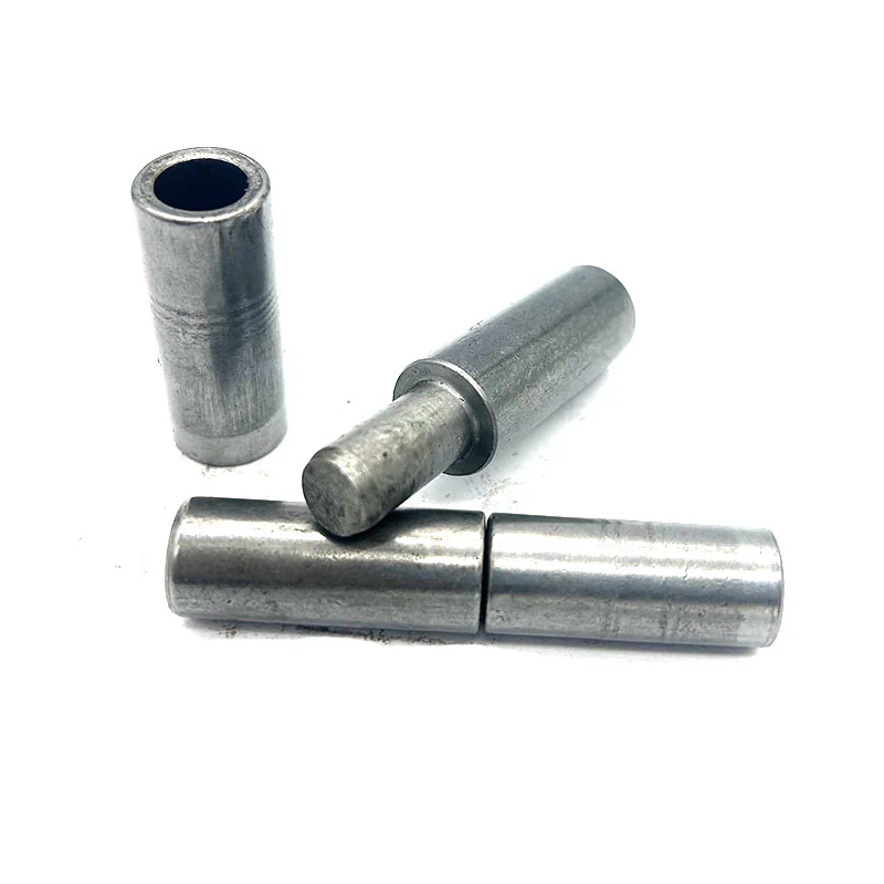
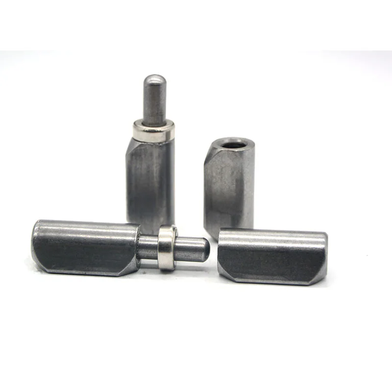
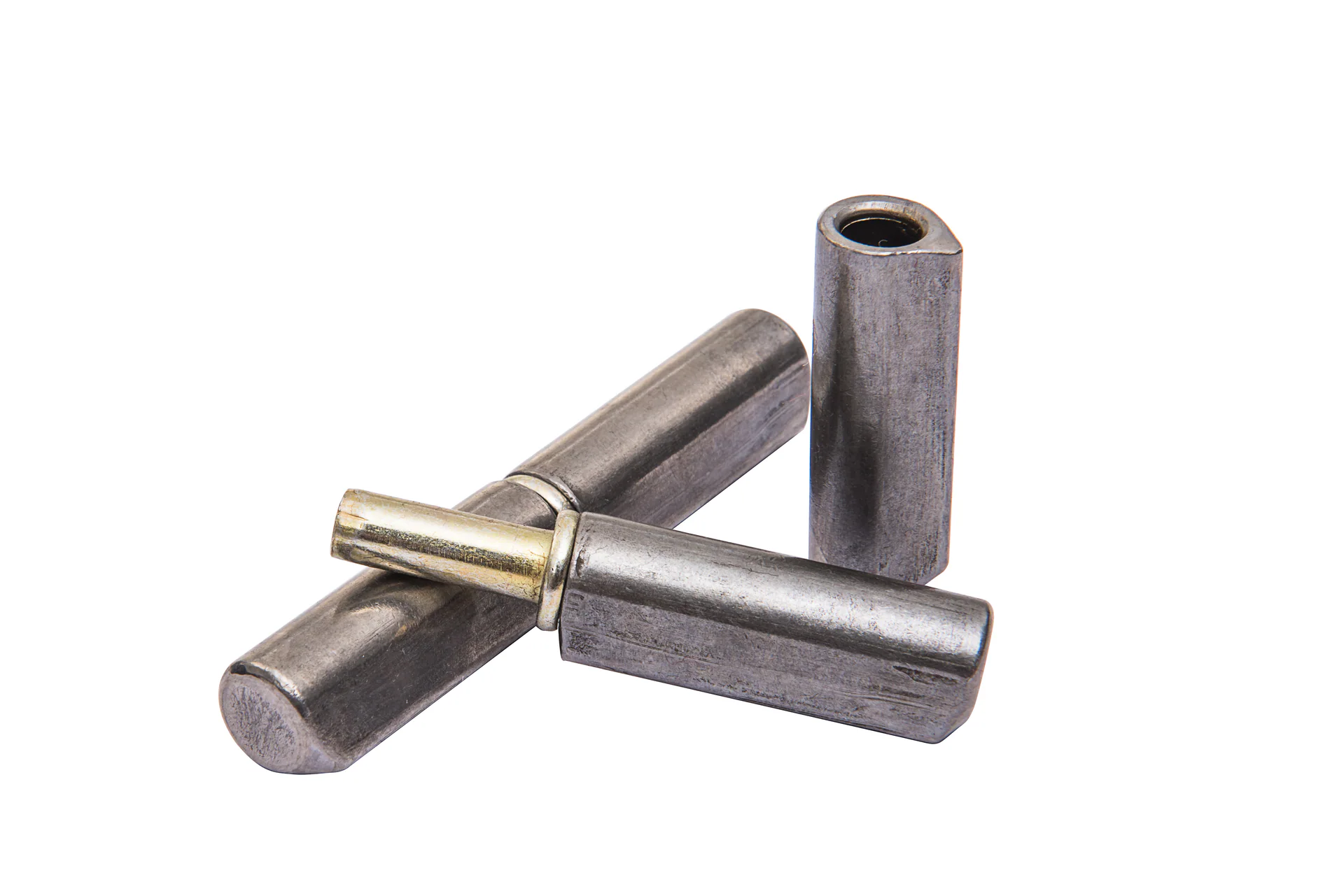
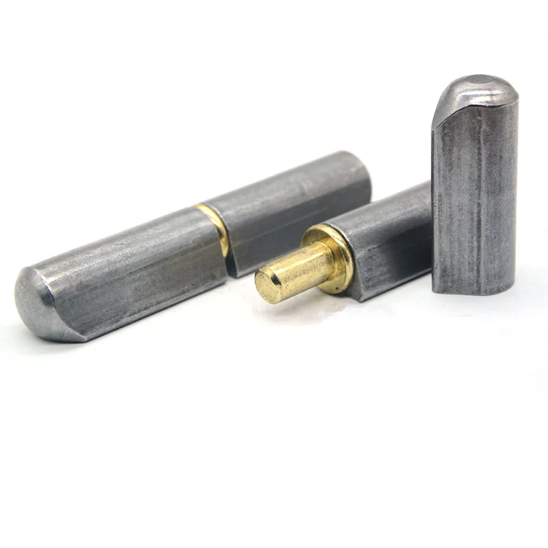
In heavy fabrication, cylindrical and teardrop barrel joints represent the standard for permanent, high-integrity rotational connections. These hinges consist of two solid body halves—a male bottom barrel housing a fixed or pressed pin, and a female top barrel acting as the rotating socket.
Understanding the mechanical naming conventions across fabrication industries is essential for clear design communication. For terminology clarification across trade descriptions, consult our reference on Bullet and Barrel Weld-On Hinge Names and Terminology.
The geometric profile of the barrel determines how the hinge mates with surrounding structural members:
- Cylindrical Round Barrel Profile: Features a uniform circular outer diameter. This compact, symmetrical geometry is ideal for welding into the radius corner of square box tubing, thick structural steel jambs, or heavy plate framing where direct line-contact welding is supported by robust backing material.
- Teardrop (Water-Drop) Profile with Integrated Weld Flange: Features an extruded triangular welding lip extending outward from the cylindrical body. The extended lip positions the weld bead away from the internal cylindrical pin bore, providing a thermal barrier during fabrication and built-in standoff clearance along formed sheet metal flanges or door perimeter returns.
Both profiles serve complementary structural roles in modern manufacturing. While cylindrical barrels offer a compact footprint for heavy structural framing, teardrop profiles provide thermal management and offset clearances for thin-wall enclosures. For detailed design rules on mounting these profiles to sheet metal without thermal distortion, review our fabrication guide on Welding Hinges to Sheet Metal Doors.
For standard body lengths, outer diameters, and pin dimensions across both profile styles, reference our technical specification guide on Weld-On Hinge Sizes and Dimensional Standards.
When should an engineer specify a teardrop profile barrel hinge instead of a standard cylindrical profile?
An engineer should specify a teardrop profile when attaching hinges to formed sheet metal doors, narrow return flanges, or sealed enclosure cabinets where the extended weld lip prevents welding heat from distorting the internal pin bore and provides natural standoff clearance for door perimeter gaskets. Standard cylindrical round profiles are preferred on thick structural box tubing, structural channels, and heavy steel framing where symmetrical mounting and compact footprint are required.
Fixed vs. Demountable Joint Design: Integral Pins vs. Lift-Off Assemblies
A major functional classification in industrial hinge design is whether the joint creates a permanently captive connection or allows rapid, tool-less door removal.
In fixed or captive pin connections, the central pin is permanently secured within both hinge halves using retaining rings, welded caps, or dual-flanged leaves. Fixed joints prevent unauthorized door removal, resist upward tampering forces, and maintain precise spatial alignment in high-vibration applications such as vehicular transit doors and heavy mobile machinery.
In demountable lift-off connections, the female top barrel separates freely from the male bottom pin barrel simply by lifting the door leaf vertically along its rotational axis. This design allows operators to detach heavy access doors during routine maintenance, surface finishing, or field assembly without unbolting hardware. When designing demountable assemblies, engineers must ensure adequate overhead vertical clearance and verify proper left-hand or right-hand door orientation.
For comprehensive rules on handing, pin orientation, and overhead clearance calculations for detachable door systems, consult our detailed resource on Lift-Off Weld-On Hinges Selection and Handing Guide.
What operational factors dictate whether to use a captive pin or a lift-off separable hinge joint?
The decision depends on security requirements, overhead spatial clearance, and maintenance frequency. Captive pin joints are required where upward door removal must be mechanically prevented for security or where dynamic operating vibration could lift the door leaf. Lift-off joints are chosen when rapid, tool-free door detachment is needed for component maintenance, tight equipment washdown, or off-site surface powder coating, provided sufficient overhead clearance exists above the pin height.
Structural Attachment Interfaces: Welded, Fastened, and Hybrid Mounts
How an industrial hinge joins the door leaf and frame jamb dictates structural joint rigidity, assembly labor, field adjustability, and long-term joint integrity.
- Direct Welded Joints (Weld-On Interface): The hinge barrel is fused directly to structural steel or stainless steel framing via fillet or stitch welding. Direct welding eliminates mechanical fasteners that can loosen under vibration, achieves maximum shear strength, and delivers a sleek, low-profile exterior.
- Mechanically Fastened Joints (Bolt-On Interface): The hinge body incorporates pre-drilled through-holes, countersinks, or threaded studs secured by high-tensile bolts. Bolted joints permit field replacement without cutting tools and enable installation on pre-painted or non-weldable materials.
- Hybrid / Standoff Plate Connections: The hinge barrel is factory-welded to an intermediate mounting plate, which is subsequently bolted or slotted into the main machine frame. This hybrid approach combines the ruggedness of barrel construction with three-axis field adjustability.
To evaluate assembly costs, labor requirements, and maintenance tradeoffs between attachment types, review our in-depth comparison on Weld-On vs. Bolt-On Hinges. When installing hinges on heavy-duty mobile machinery, perimeter barriers, and access closures, reference our engineering overview on Weld-On Hinges for Gates, Trailer Doors, and Ramps.
Accurate multi-hinge coaxial alignment during fabrication is critical to prevent mechanical pin binding and excessive operating torque. Follow the step-by-step mandrel setup procedures outlined in our guide on Weld-On Hinge Alignment and Removal Clearance.
Bearing Interfaces, Lubrication Provisions, and Environmental Sealing
The internal interface between the rotating barrel halves governs rotational friction, service lifespan, and resistance to environmental degradation.
Engineers must select the internal bearing configuration based on cycle frequency and operating environment:
- Solid Brass or Bronze Thrust Washers: Standard sacrificial low-friction spacer offering reliable performance in moderate-duty, manual-access applications.
- Sintered Bronze Oil-Impregnated Bushings: Self-lubricating porous bronze sleeves that release lubricating oil during rotation, ideal for high-cycle doors requiring maintenance-free operation.
- Hardened Ball Bearing / Thrust Bearing Assemblies: Precision rolling-element assemblies engineered for heavy structural doors, minimizing manual opening torque under extreme axial gravity loads.
- Integrated Grease Zerk Fittings: Threaded or drive-fit grease lubrication ports that enable periodic purging of contaminants and replenishment of high-pressure grease in harsh industrial or marine environments.
For comprehensive technical selection criteria on internal thrust interfaces and pin materials, consult our engineering guide on Bearing, Pin, and Washer Selection for Weld-On Hinges. For lubrication schedule planning and grease port design rules, explore our reference on Grease Fitting and Lubrication Design for Weld-On Hinges.
Material selection directly impacts galvanic corrosion resistance and weld compatibility. Review our material pairing guide on Weld-On Hinge Materials and Finishes for carbon steel, austenitic stainless steel, and marine-grade stainless steel fabrication rules.
What bearing interface should be specified for high-cycle industrial doors carrying heavy axial loads?
For heavy high-cycle industrial doors, design engineers should specify hardened ball bearing thrust packs or sintered oil-impregnated bronze bushings combined with an integrated grease zerk fitting. This assembly minimizes manual swing torque, prevents galling between rotating barrel faces, and allows periodic purging of abrasive environmental particulates through routine grease replenishment.
Engineering Specification Workflow and Drawing Requirements
Translating functional hinge joint requirements into an unambiguous engineering drawing package prevents costly shop-floor errors and ensures consistent vendor manufacturing.
For step-by-step guidance on creating 2D/3D CAD submittal packages and tolerance specifications for custom hardware quoting, review our complete technical checklist on Preparing Hinge Drawing Dimension Requests.